Electrochemistry Aluminum Corrosion Stress Corrosion Cracking Review Papers
![]()
Stress Corrosion Cracking of Friction Stir-Welded AA-2024 T3 Alloy
by 1,2,3  , 4 , iv , four , 1,2,iii,* , i,2,3 and 1,2,3
1
Section of Applied science and Applied Sciences, Academy of Bergamo, 24044 Dalmine (BG), Italy
2
National Interuniversity Consortium of Materials Science and Technology (INSTM) Research Unit of measurement of Bergamo, 24044 Dalmine (BG), Italy
iii
Center for Colloid and Surface Science (CSGI) Enquiry Unit of Bergamo, 24044 Dalmine (BG), Italy
iv
Information and Product Engineering, Department of Management, Academy of Bergamo, 24044 Dalmine (BG), Italian republic
*
Writer to whom correspondence should be addressed.
Received: 2 May 2020 / Revised: 28 May 2020 / Accustomed: 3 June 2020 / Published: 8 June 2020
Abstruse
The paper is devoted to the study of stress corrosion swell phenomena in friction stir welding AA-2024 T3 joints. Constant load (CL) jail cell and slow strain rate (SSR) tests were carried out in aerated NaCl 35 g/L solution. During the tests, open circuit potential (OCP) and electrochemical impedance spectroscopy (EIS) were measured in the different zones of the welding. The results evidenced initial applied nobilty of the nugget lower compared to both rut-afflicted zone and the base of operations metal. This effect can be mainly ascribed to the aluminum matrix depletion in copper, which precipitates in class of copper-rich 2nd phases. In this zones, no stress corrosion cracking was noticed, but well-axiomatic stress-enhanced intergranular corrosion occurred. This is due to the uneven distribution of platic deformation during the slow strain rate tests. College strain values are localized at the rut affected zone, where softening occurs. On the opposite, stress values at the nugget are not sufficient to favor both the initiation and propagation of stress corrosion cracks. In the range of processing parameter studied in this experimental piece of work, the stress corrosion keen susceptibility of the friction stir welding (FSW)-ed blend is so similar to that of the base metallic.
ane. Introduction
Friction stir welding (FSW) is a solid-state joining process that is gaining a lot of attention peculiarly for high-strength historic period-hardening aluminum alloys, in which mechanical properties are strictly dependent upon oestrus treatments at relatively lower temperatures [1,2,3,four]. The joint is produced by the friction generated between a rotating pin put directly in contact with the base metallic. The temperature of the cloth increases significantly in the contact zone without melting the material itself [five]. The increase in temperature increases the fabric deformability, thus assuasive the mixing of the two sides of the joint [6]. The thermo-mechanical action causes the material recrystallization that is localized in the fundamental area of the weld, chosen nugget characterized by outstanding tensile properties [7,8]. The zones close to the asset, which has the microstructure contradistinct both by the action of the mechanical straining and the thermal event, is called thermo-mechanically affected zone (TMAZ); after this zone, moving away from the nugget toward the base metal, there is an area that has non undergone mechanical straining, but only heating and therefore it is called estrus-affected zone (HAZ). The microstructure and extension of these zone, nugget, TMAZ, and HAZ, depend on the size and shape of the pin, the thickness of the sail, and the welding parameters, in item the force exerted on the pin, its rotation speed, and feed rate [9,10]. Depending on the tool rotation side, "advancing side" and "retreating side" are defined [11]. Lot of efforts take been paid to written report the effect of the tool rotation on both the extension of these zones and the effects on mechanical properties in function of the process parameters, i.e., speed and feed rate [12,xiii,14]. Among all the aluminum alloys, series 2XXX, 6XXX [15], and 7XXX [16,17] are the near affected by the microstructure and mechanical properties modification induced by FSW, because their resulting microstructure is a combination between the original atmosphere and the thermomechanical alterations induced by FSW process. Microstructural modifications are relevant across the welding and both mechanical and corrosion behavior [xviii] at the nugget, TMAZ, and the HAZ are strictly dependent upon the process parameters.
The combined action of applied stress and corrosive surroundings can too promote stress corrosion cracking (SCC) in susceptible alloys [19,20,21,22] and the effect of the microstructural modification induced by FSW on the intrinsic susceptibility of such alloys is yet far to be completely understood. The college number of works are on the SCC of blend 7XXX just, in the cognition of the authors, only few papers reported the SCC beliefs of FSW joints in AA-2024.
Wang et al. reported SCC uprising on FSW AA-2024-T3 in the interface betwixt the nugget and the TMAZ in 3.5 wt.% NaCl solution. The stress corrosion cracks were nucleated past pitting. The SCC susceptibility of the FSWed joints increases with increasing travel speed, owing to the increment of the size of 2d phase particles. A SCC mechanism controlled past the metal anodic dissolution at the OCP and hydrogen accelerated metal embrittlement in the active zones was suggested [23] In a previous newspaper of the authors, no stress corrosion cracking was observed on four point bent beam specimens after 1500 h of exposure in NaCl 35 g/L, but the intergranular corrosion assail became penetrating in the presence of loading, giving rise to stress-enhanced intergranular corrosion of the alloy [14].
The aim of this work is to study the stress corrosion dandy susceptibility of FSWed AA-2024 T3 aluminum blend. Electrochemical tests and free corrosion potential measurements were carried out during SCC test to appraise corrosion phenomena occurring during exposure.
2. Materials and Methods
2.1. Preparation of the Welds
Aluminum sheets (size 200 mm × 80 mm × 4 mm thickness) were welded past using a tool with smooth aeroplane shoulder (16 mm diameter) and pin having a frustum of cone shape (pin maximum and minimum diameters equal to 6 and iv mm, pinnacle equal to 3.8 mm) (Effigy 1). The rotational speed (S) of the tool was fixed at 1500 rpm and feed rate (F) was ten mm/min. The set-up of the welding process was reported in previous works by authors [14,18,22,24]. The mechanical backdrop of the base materials and the welded joints are shown in Table 1. For the FWSed specimens, only the ultimate tensile strength (UTS) is reported, because it was not possible to evaluate the yield strength (YS) owing to the localization of the plastic straining of the specimens in the TMAZ/HAZ zone. The decrease in the mechanical properties at the thermomechanical and estrus afflicted zones is the result of the modification in the microstructure of the alloy, with solubilization and reprecipitation of the straightening second phases, as reported in previous works by authors [x,fourteen,eighteen,22,24]. A good reproducibility was observed in the tensile strength of the FSWed joints, thus confirming the absence of macroscopic defects aslope the weld.
two.2. Abiding Load Tests
Constant load (CL) tests were carried out on dog bone shaped specimens with 8 mm width, iv mm thickness, and 82 mm gage length with the weld positioned at the center of the cuff length (Figure ii). The specimens were inserted in a double compartment cell with a window to expose most l% of the central area (Figure 3a,b). All the compartments were filled with aerated 35 g/L NaCl solution, at 25 °C. The solution was constantly recirculated by ways of a pump. The configuration of the jail cell was chosen in order to monitor one side the open up circuit potential (OCP) and carry out the electrochemical impedance spectroscopy (EIS) test on the other side at the aforementioned time.
The OCP monitoring was done by means of homemade three Ag/AgCl references electrodes with E = +0.200 V vs. NHE (normal hydrogen electrode). The results were presented later conversion every bit the saturate calomel electrode (SCE-Eastward = +0.240 V vs. NHE, Amel Musical instrument, Milano, Italy). The data were registered past a Ivium CompactStat instrument; the sampling frequency was varied during the experiment from one measurement per 2d in the initial instants and during the loading phases of the specimen to a 10-h monitoring, with acquisition of ane point per minute every 100 or 200 h, during maintenance of the constant load of the specimens. The EIS tests were performed using an Ivium CompactStat musical instrument. Sinusoidal signal with 0.010 V amplitude in the frequencies range between ten kHz and 10−2 Hz was practical. EIS tests were carried out on the CL speciemens just dipped, afterwards 24, 48 (before and after loading the specimen), 480, 504 (earlier anf afterwards increase the load on the specimen), 552, and 650 h (before and later to un-load the specimen).
The specimens were loaded past means of a tensile testing machine with a double lever arm (Figure 3c), according to NACE TM 0177-2005 Method A, the loads were imposed by adding weights to the lever, the lever forcefulness had previously been calibrated through a calibrated load jail cell with ten Northward accuracy. The testing procedure is every bit following. The specimen was initially positioned in the cell, the testing solution was inserted, and the showtime EIS spectrum was registered. The second EIS spectrum was measured afterwards 24 h, the 3rd after 48 h; after the third EIS measurement, the specimen was loaded at 50–55% UTS of the FSWed joints, and the EIS measure immediately repeated. This load was chosen because information technology is practically in the correspondence of the deviation from the linearity of the stress–strain curve of the weld; information technology could exist assumed that, under this stress, the less resistance zone of the gauge length becomes plastically deformed, while the other parts of the specimen remain in elastic straining. The monitoring of OCP and EIS spectrum connected for 504 h, afterward these the load was further increased in order to achieve a stress value of about the 80% of the ultimate tensile strength of the weld, thus achieving uniform plastic deformation weather condition along the cuff length of the specimen. The load was and so maintained for 650 h.
At the end of the exposure menses, the specimens were unloaded, cleaned, and observed under the scanning electron microscope (SEM, Zeiss EVO 40, Oberkochen, Germany) with energy dispersive spectroscopy (EDS) Oxford X-Deed in gild to analyze the corrosion products morphology and limerick. Metallographic cross sections along the longitudinal direction were besides analyzed. The approximate length was cut from the specimen, so longitudinally sectioned using a metallographic cutting machine (Metkon Servocut, Bursa, Turkey) in the central office. The section was embedded in resin and grinded with emery paper and polished with colloid alumina until 0.one μm of roughness. The metallographic section was observed by a Nikon optical microscope and the SEM without metallographic attack and later attack with Keller reagent.
two.3. Wearisome Strain Rate Tests
The deadening strain rate (SSR) tests were carried out by using specimens of the same dimensions as for CL tests. The SSR tests were also performed on AA-2024 T3 base fabric for comparison.
The tests were carried out past means of a bootleg SSR testing machine with four independent loading stations. The load is applied through an electric motor and reduction gears that can impose displacement rates between 5 × ten−7 and 5 × x−three mm/s. The calibration of the cells is performed independently. Acquisition arrangement (spider viii HBM Italy, Milano, Italy) read the load and a part of time; the displacement of the tensile grip is evaluated multiplying the displacement charge per unit for the fourth dimension. A displacement rate of 8.2 × ten−4 mm/s, corresponding to 10−6 s−1 average strain rate forth the cuff length, was chosen. SSR tests were carried out co-ordinate to the ASTM 129-00 (2013), exception for the specimen'due south geometry that was changed to exam all the weld. The cell was like those used for the CL tests, with the aforementioned configuration of the electrodes, but smaller than that for CL tests, to be settled under the SSR machine, filled with an aerated solution of 35 g/L NaCl. No EIS spectra were obtained during this test considering the OCP did non remain abiding. At the stop of the tests, the specimens were washed in distilled water and rinsed in acetone to permit the ascertainment of the fracture surface nether the SEM. Then the specimens were longitudinally sectioned for the metallographic observation with the same process illustrated for the CL examination.
2.iv. Electrochemical Characterizations of the Unlike Zones of the Weld
For comparing, EIS and OCP measurements were performed on the separated unlike zones of the FSW joints: the nugget, the HAZ/TMAZ (it was not possible to cutting the specimens separating these zones), and the base textile in unloaded status. The weld was cut as illustrated in Figure 4; the isolate specimens with the asset, the TMAZ/HAZ zone, and the base textile were connected with an external wire and so cold mounted with epoxy resin. The exposed surface of the specimen was xx × 20 mm2. It was grounded with emery paper and then polidhed with colloidal alumina upwardly to 0.iii μm. The specimens were dipped in separate glass cells in aerated 35 g/L NaCl (Carlo Erba, RPA grade, Cornaredo, Italy) solution. Standard saturated calomel electrode (SCE E = +0.240 V vs. NHE, Amel Instrument, Milano, Italy) was positioned at the surface of the specimens by using a Luggin capillary to recoup the ohmic drib in the electrolyte. Electrochemical impedance spectroscopy (EIS) tests were performed with the same procedure used for on the CL test.
3. Results and Discussion
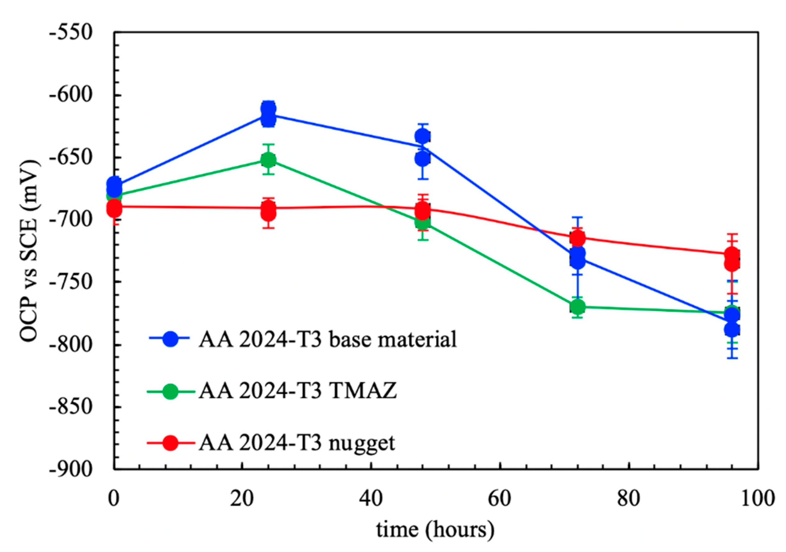
Figure v shows the OCP measurements in aerated NaCl solution at the nugget, the HAZ/TMAZ, and the base material with regard to exposure time.
Similar values of the OCP were measured on the three different zones just after dipping. The nugget showed constant OCP values during all the exposure periods. Different behavior was observed for the base material and the rut-affected zones (HAZ/TMAZ), which showed an initial increase of OPC followed by a decrease of virtually 150 mV.
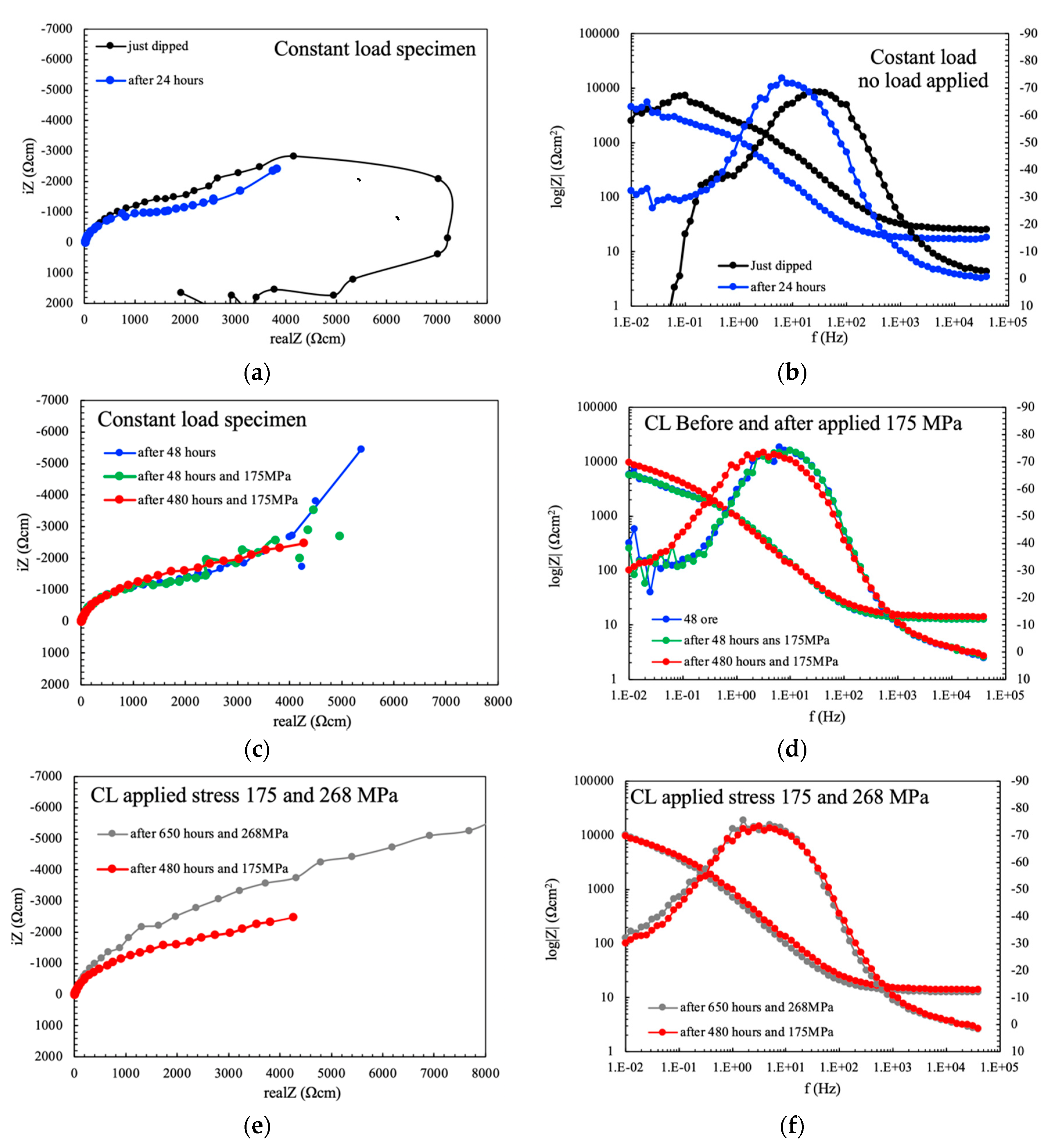
Figure 2 shows the EIS spectra for the specimens obtained from the different zones of the weld with regard to exposure time. The spectra collected at the asset are quite different compared to the base textile and TMAZ simply later dipping. The Nyquist plot shows two overlapped capacitive loops, and an inductive ane at very low frequencies, whereas the base of operations material and the TMAZ presented a capacitive loop and diffusive behavior at very low frequencies (Effigy 6a). The Bode diagram (Effigy 6b) shows the highest value of the impedance modulus of the base materials, indicating a stable passive status. Conversely, the values of the impedance modulus of the nugget and the TMAZ decrease at the low frequency, thus indicating activation of the metallic surface during low frequency measurements. All the specimens showed two phase constants, i at intermediate frequency and the other at very low frequencies.
After only 24 h of immersion, the shape of EIS spectra significantly changed (Figure 6c,d). The amplitude of the EIS loops in Nyquist plot decreased significantly for all the different zones of the weld. Deviating behavior was still observed for the base metal and the TMAZ, while a 2d capacitive loop can exist distinguished for the nugget—but flattened—and the inductive loop disappeared. All the specimens showed only one phase abiding, only the frequency range is lower compared to just dipped conditions. An increase in phase can be noticed at very depression frequency for the base fabric and the TMAZ, thus indicating that a second phase constant could exist present at very low frequencies. The impedance modulus accomplished the values of 10iv Ωcm2 for all the zones of the weld, meaning that activation occurred as well on base metal and the TMAZ.
After 72 h of immersion, the EIS spectra became practically overlapped, with only a slight difference between the impedance modulus of the nugget with respect to the base material and the TMAZ (Figure 6e,f). Well evident diffusive behavior can be noticed at very depression frequencies considering of the presence of corrosion products deposit.
These results seem to evidence an initial higher activity of the nugget with respect to the other zones, merely these differences become negligible at longer exposures. Afterward the tests, all the specimens showed full general corrosion morphologies.
The behavior significantly modifies every bit loading is applied. The corrosion potential showed sudden decrease at the application of monoaxial constant load, as reported in Figure seven. The effect is attributable to the breakup of the thick, porous, and not adherent calibration of aluminum oxide formed on specimens later prolonged exposures, which exposes the aluminum matrix direct to the aggressive environment. The potential approached the steady state value—i.e., the value in unloading weather—considering of cocky-healing effect of corrosion products of aluminum. The subtract in the corrosion potential is more pronounced when the specimens are strained in the plastic field.
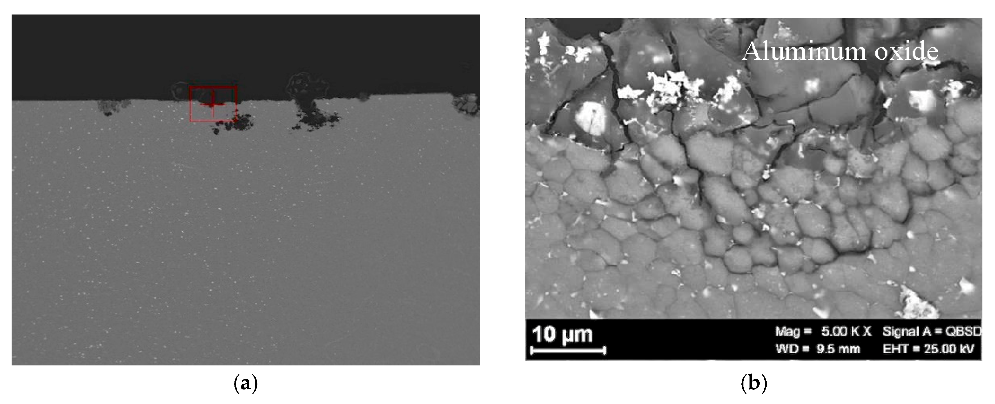
Specimens failure was not observed under constant loading for 650-h exposure. The analysis of the specimens after the tests showed an intergranular assail in the nugget near the zone of beginning of the TMAZ (Figure 8 and Figure 9).
The EIS spectra collected on CL specimens showed certain dissimilar behavior merely afterwards dipping and after 24 h (Figure 10a,b). The spectra mainly approach that of the nugget (compare Figure 10a,b with Figure 6a,b). It can and so be stated that EIS tests carried out during CL tests are mainly affected past the most active zone of the joint—i.eastward., the nugget. The specimen just subsequently dipping presents two overlapped capacitive loops and an inductive ane (Figure 10a)—typical of non-stationary OCP values during early exposures EIS tests (Figure 10b). Subsequently 24 h, the Nyquist diagram presented a well-evident diffusive behavior (compare Figure 10c,d to Figure 6c,d). The increment in the load does not alter the EIS spectra, that are overlapped to the status without applied load after 24-h exposure (Figure 10c–f), thus confirming that the corrosion process at longer exposures is only limited past the presence of the pseudo-passive film past corrosion products that are able to heal the cracks promoted past loading.
These results are in understanding with those obtained in previous works [14,22,24]. It was observed that the OCP did not modify in four indicate bent beam (4PBB) specimens in un-loaded or loaded atmospheric condition at the 80% of the ultimate tensile strength of the weld (Figure 11). The specimens were loaded before the immersion. On the contrary, differences betwixt the EIS spectra of united nations-loaded and loaded specimens were observed only at very early exposures. This was mainly attributed to the presence of corrosion products calibration formed on the surface of the specimens, that hindered the EIS signal response. On 4PBB specimens, the corrosion procedure was mainly localized at the nugget, with wide and shallow deep morphology on the united nations-loaded specimens and stress-enhanced intergranular morphology on loaded specimens [22]. The issue of the practical load on intergranular corrosion initiation and propagation in alloy AA-2424 T3 was first highlighted by Zhang and Frankel [25,26]. However, the entire surface of the specimens is covered with a continuous merely porous layer of corrosion products every bit the exposure time increases. This is well evident in the EIS spectra that are practically overlapped as they are mainly governed by deviating phenomena occurring at the corrosion products scale [22].
The OCP of the FSWed AA-2024 T3 alloy under tiresome strain rate conditions, (Figure 12) modifies in office of the applied monotonic tensile stress. A slight subtract in the values tin be noticed equally the strain values lay in the elastic field. A sharp decrease was noticed—i.eastward., 100–250 mV—at the YS. Exceeding the YS, the OCP increases up to the values recorded in the elastic field, until the rupture. The specimen breaking did not occur at the nugget that is characterized by college tensile strength, simply in the heat affected zone. Because of this consideration, it tin be derived that the attack observed at the nugget (Figure 13) did not reach sufficient depth to promote the specimen rupture, as the plastic deformation mainly have identify in the softened zones, typical of the HAZ/TMAZ. Consequently, the effect of FSW on the blend microstructure and on the mechanical properties significantly bear on too the stress corrosion cracking susceptibility of the alloy.
SSR tests performed on commercial AA-2024 T3 alloy showed a completely different behavior compared to FSWed. The OCP values are stable at more noble values compared to FSWed, without the occurrence of stress corrosion cracks (Effigy xiv).
For both the weld and the commercial AA-2024 T3 alloy, the time-to-failure is longer in NaCl solution compared to air. All the tests were twice repeated with like results. Information technology could be hypothesized that agile corrosion in NaCl solution is stimulated at the dislocations, thus generating vacancies able to accelerate the intrinsic mobility and thus the plastic deformation, as already evidenced by other authors that named this miracle as anodic attenuation of strain hardening [27,28].
FSW modify the microstructure of the alloy and its electrochemical and stress corrosion cracking beliefs, consequently. In the base cloth, both macro-precipitates and nanoprecipitates are present (Figure 15) [ix,11]. The last ones are produced considering of solution annealing and natural aging. The macro-precipitates are mainly produced by main solidification processes and are not solubilized during estrus handling [29]. They are considered to exist responsible of the short-term electrochemical behavior of the alloy every bit it is well-known that the interface betwixt these particles and the matrix is particularly active because of its unlike applied nobility [xxx].
The master second phases of AA-2024 T3 alloy are S phases (Al2CuMg) and Al-Cu-Mn-Fe [xxx,31]. By and large, the formers are anodic with respect to the aluminum matrix because of the presence of magnesium, while the latter, consisting of more noble elements such as copper, iron, and manganese, are cathodic. South stage is particularly active and college corporeality of this phase is more often than not present. It quickly reacts with the solution but after dipping, thus leading to the dissolution of magnesium. Every bit a result, the alloy surface becomes richer in copper and the corrosion potential tends to increase. At longer exposures, corrosion initiation occurs in some areas, and so propagate in the aluminum matrix. Thick layer of insulating corrosion products so forms on the metal surface, which hinder the corrosion process as a effect of the settlement of pseudo-passivation conditions. EIS spectra well testify the formation of the corrosion products layer as a deviating behavior at very depression frequencies that is compatible with the hypothesized mechanism. The charge per unit-determining step of the corrosion process is so mainly related to the improvidence processes within the porous non-conductive scale. The phase peaks at low frequencies tin can be related to the dissolution of the intermetallics at metallic/particle interface [32].
During the welding process, recrystallization induced by the thermomechanical activity occurs mainly at the asset. In these zones, dissolution of nanometric S phase precipitates occurs, which tin re-precipitate in course of micrometric particles, conspicuously detectable at the scanning electron microscope (Figure 16). These precipitates are mainly located at the recrystallized grain boundaries. The presence of copper in the supersaturated solid solution in the aluminum matrix gives rise to initially nobler OCP values compared to the nugget and HAZ. The enriching in copper because of the preferential dissolution of magnesium in S-phase, is responsible for the initial increasing of the OCP, but the rapid activation of corrosion phenomena at precipitate-costless zones causes the decrease in the OCP after a few hours of immersion.
The anodic dissolution, catalyzed likewise by the presence of precipitates forth the grain boundaries, is considered to be the main SCC mechanism in high forcefulness 2xxx (Al–Cu–Mg) serial alloys [33]. The galvanic interaction betwixt the particles and the surrounding matrix causes the preferential dissolution of the anodic particles or the dissolution of the adjacent matrix surrounding nobler particles. Development of hydrogen always occurs in actively growing localized corrosion sites and cracks. The absorption of hydrogen into metals leads to the possibility of crack propagation by hydrogen embrittlement (HE) [33,34,35,36,37,38,39,40,41,42,43,44]
In this way, FSW modifies the microstructure of AA 2024-T3 alloy, thus making the nugget more susceptible to SCC than the base cloth. However, the HAZ and TMAZ are characterized by lower tensile strength compared to both the asset and the base of operations metallic. The awarding of load causes the occurrence of microcracks at the nugget which do not propagate as the fracture is localized in zones with lower tensile strength, i.e., plastic deformation is significantly shifted in the HAZ/TMAZ. Therefore, the strain at the asset is limited and pseudo-passive film can exist restored in such conditions, as demonstrated by the increases in the OCP.
Similar consequence was observed on the same alloy past Ferri et al. on 4PBB loaded in elastic field during potentiodynamic tests [45]. This was attributed to dissolution mechanism assisted by the mechanical stress, according to the chemomechanical theory of Gutman [46]. The weakening of the effect as load levels approach the YS was ascribed to a bulwark activeness of corrosion products film hindering the go out of dislocations from the surface and thus inhibiting the creation of fresh surfaces [45,47]. The stress enhanced intergranular corrosion at nugget is inhibited equally the specimens are plastically strained in TMAM/HAZ zones. In this way, the SCC phenomena cannot be observed, and the specimen fails in a ductile manner in the TMAZ/HAZ, similarly to the test in air.
In other words, the decreasing of tensile backdrop in TMAZ/HAZ acquired a deformation in these zones, counteracting the hypothetically higher stress enhanced intergranular corrosion susceptibility of the asset.
A like SCC behavior for joint and base metallic of FSWed AA2219-T87 through wearisome strain rate tests (SSR) is reported past Paglia and Buchheit [48]. On the contrary, intergranular fracture in the interface between the nuggets and TMAZ of welded joints tested in 0.vi M NaCl solution is reported by Wang et al. [23]. The concluding authors reported that the tests in air showed ductile fracture in the same zone. This unlike behavior could be attributed to the different welding parameters. The same authors reported that the stress corrosion cracking (SCC) susceptibility of the FSW 2024-T4 aluminum blend joint increased with feed rate due to the increase of the second phases size.
4. Conclusions
The paper analyzed stress corrosion cracking phenomena in friction stir welding AA-2024 T3 joints. Constant load (CL) cell and slow strain rate (SSR) tests were carried out in aerated 35 chiliad/L NaCl solution. During the tests, open excursion potential and electrochemical impedance spectroscopy were measured in the different zones of the welding.
The FSW process significantly modifies the microstructure of the alloy, and therefore, its corrosion and stress corrosion cracking beliefs.
The practical load enhances the intergranular corrosion at the asset of the AA 2024-T3 alloy owing to the presence of micrometric copper-rich precipitates at the edge of the recrystallized grains. In this zones, no stress corrosion nifty was noticed, simply well-evident stress-enhanced intergranular corrosion occurred. Moreover, the applied strain is preferentially localized at HAZ/TMAZ zones which are characterized by lower tensile forcefulness compared to the nugget. Higher strain values are then localized at the heat-affected zones, where softening occurs.
Considering of these contrasting effects, information technology is possible to country that the stress corrosion bully susceptibility of the FSW-ed alloy is then similar to that of the base metallic in the range of processing parameter studied in this experimental work.
Writer Contributions
Methodology, S.L., C.T. and S.B.; investigation, South.L., C.T. and S.B.; data curation, G.D. and Thousand.C.; all the authors contributed to writing the original typhoon of the paper. Writing—review and editing T.P., C.One thousand. and M.C.; supervision, T.P. and C.One thousand.; project administration, T.P. All authors have read and agreed to the published version of the manuscript.
Funding
This enquiry received no external funding.
Conflicts of Interest
The authors declare no conflict of interest.
References
- Thomas, West.M.; Nicholas, E.D. Friction stir welding for the transportation industries. Mater. Des. 1997, eighteen, 269–273. [Google Scholar] [CrossRef]
- Mishra, R.S.; Ma, Z.Y. Friction stir welding and processing. Mater. Sci. Eng. R Rep. 2005, 50, i–78. [Google Scholar] [CrossRef]
- Dawes, C.; Thomas, Due west. Friction stir process welds aluminum alloys. Weld. J. 1996, 75, 41–45. [Google Scholar]
- Murr, L.; Li, Y.; Trillo, E.; McClure, J. Primal Issues and Industrial Applications of Friction-Stir Welding. Dep. Pap. (Met. Mat.) 2000, 15, 37–48. [Google Scholar]
- Frigaard, Ø.; Grong, Ø.; Midling, O.T. A process model for friction stir welding of age hardening aluminum alloys. Met. Mater. Trans. A Phys. Met. Mater. Sci. 2001, 32, 1189–1200. [Google Scholar] [CrossRef]
- Benavides, South.; Li, Y.; Murr, 50.E.; Brown, D.; McClure, J.C. Low-temperature friction-stir welding of 2024 aluminum. Scr. Mater. 1999, 41, 809–815. [Google Scholar] [CrossRef]
- Jata, G.V.; Semiatin, South.50. Continuous dynamic recrystallization during friction stir welding of high strength aluminum alloys. Scr. Mater. 2000, 43, 9. [Google Scholar] [CrossRef]
- Genevois, C.; Deschamps, A.; Denquin, A.; Doisneau-Cottignies, B. Quantitative investigation of precipitation and mechanical behaviour for AA2024 friction stir welds. Acta Mater. 2005, 53, 2447–2458. [Google Scholar] [CrossRef]
- Sutton, M.A.; Yang, B.; Reynolds, A.P.; Taylor, R. Microstructural studies of friction stir welds in 2024-T3 aluminum. Mater. Sci. Eng. A 2002, 323, 160–166. [Google Scholar] [CrossRef]
- Bocchi, S.; D'Urso, Yard.; Giardini, C.; Maccarini, G. Furnishings of Cooling Weather on Microstructure and Mechanical Properties of Friction Stir Welded Butt Joints of Different Aluminum Alloys. Appl. Sci. 2019, nine, 5069. [Google Scholar] [CrossRef]
- Fonda, R.Westward.; Bingert, J.F.; Colligan, 1000.J. Evolution of grain structure during friction stir welding. Scr. Mater. 2004, 51, 243–248. [Google Scholar] [CrossRef]
- Zettler, R.; Lomolino, Due south.; Dos Santos, J.F.; Donath, T.; Beckmann, F.; Lippman, T.; Lohwasser, D. Effect of tool geometry and process parameters on cloth flow in FSW of AN AA 2024-T351 alloy. Weld. World 2005, 49, 41–46. [Google Scholar] [CrossRef]
- Paidar, Yard.; Khodabandeh, A.; Sarab, 1000.L.; Taheri, M. Effect of welding parameters (plunge depths of shoulder, pin geometry, and tool rotational speed) on the failure mode and stir zone characteristics of friction stir spot welded aluminum 2024-T3 sheets. J. Mech. Sci. Technol. 2015, 29, 4639–4644. [Google Scholar] [CrossRef]
- D'Urso, Thou.; Giardini, C.; Lorenzi, Due south.; Cabrini, M.; Pastore, T. The influence of process parameters on mechanical properties and corrosion behaviour of friction stir welded aluminum joints. J. Manuf. Process. 2018, 35, one–15. [Google Scholar] [CrossRef]
- Sato, Y.South.; Kokawa, H.; Enomoto, Thou.; Jogan, Due south. Microstructural evolution of 6063 aluminum during friction-stir welding. Met. Mater. Trans. A Phys. Met. Mater. Sci. 1999, xxx, 2429–2437. [Google Scholar] [CrossRef]
- Mahoney, Yard.W.; Rhodes, C.Yard.; Flintoff, J.G.; Spurling, R.A.; Bingel, W.H. Properties of friction-stir-welded 7075 T651 aluminum. Met. Mater. Trans. A Phys. Met. Mater. Sci. 1998, 29, 1955–1964. [Google Scholar] [CrossRef]
- D'Urso, K.; Giardini, C. Thermo-Mechanical Characterization of Friction Stir Spot Welded AA7050 Sheets by Means of Experimental and FEM Analyses. Materials (Basel) 2016, 9, 689. [Google Scholar] [CrossRef] [PubMed]
- D'Urso, Yard.; Giardini, C.; Lorenzi, S.; Cabrini, M.; Pastore, T. The Effects of Process Parameters on Mechanical Properties and Corrosion Behavior in Friction Stir Welding of Aluminum Alloys. Procedia Eng. 2017, 183, 270–276. [Google Scholar] [CrossRef]
- Burleigh, T.D. Postulated mechanisms for stress corrosion cracking of aluminum alloys. A review of the literature 1980–1989. Corrosion 1991, 47, 89–98. [Google Scholar] [CrossRef]
- Gruhl, West. Stress Corrosion Swell of Loftier Strength Aluminium Alloys. Zeitschrift fuer Met. 1984, 75, 819–826. [Google Scholar]
- Holroyd, North.J.H.; Evans, J.T.; Scamans, G.M. Pre-exposure embrittlement of an Al-Cu-Mg alloy, AA2024-T351. Corros. Rev. 2015, 33, 361–372. [Google Scholar] [CrossRef]
- Bocchi, South.; Cabrini, Thousand.; D'Urso, M.; Giardini, C.; Lorenzi, South.; Pastore, T. Stress enhanced intergranular corrosion of friction stir welded AA2024-T3. Eng. Neglect. Anal. 2020, 111, 104483. [Google Scholar] [CrossRef]
- Wang, W.; Li, T.; Wang, Chiliad.; Cai, J.; Qiao, Thousand. Upshot of Travel Speed on the Stress Corrosion Beliefs of Friction Stir Welded 2024-T4 Aluminum Alloy. J. Mater. Eng. Perform. 2016, 25, 1820–1828. [Google Scholar] [CrossRef]
- Cabrini, K.; Lorenzi, S.; Bocchi, Southward.; Pastore, T.; D'Urso, G.; Giardini, C. Evaluation of corrosion beliefs of AA2024 T3 welded past means of FSW. In Proceedings of the EUROCORR 2017—The Annual Congress of the European Federation of Corrosion, 20th International Corrosion Congress and Process Safe Congress 2017, Prague, Czech Commonwealth, 3–vii September 2017. [Google Scholar]
- Zhang, W.; Frankel, G.Due south. Transitions between pitting and intergranular corrosion in AA2024. Electrochim. Acta 2003, 48, 1193–1210. [Google Scholar] [CrossRef]
- Zhang, West.; Frankel, Yard.S. Localized Corrosion Growth Kinetics in AA2024 Alloys. J. Electrochem. Soc. 2002, 149, B510. [Google Scholar] [CrossRef]
- Jones, D.A. Localized Surface Plasticity during Stress Corrosion Cracking. Corrosion 1996, 52, 356–362. [Google Scholar] [CrossRef]
- Hatamleh, O.; Singh, P.M.; Garmestani, H. Corrosion susceptibility of peened friction stir welded 7075 aluminum blend joints. Corros. Sci. 2009, 51, 135–143. [Google Scholar] [CrossRef]
- Vijaya Kumar, P.; Madhusudhan Reddy, G.; Srinivasa Rao, K. Microstructure and pitting corrosion of armor class AA7075 aluminum alloy friction stir weld asset zone—Consequence of post weld heat treatment and improver of boron carbide. Def. Technol. 2015, 11, 166–173. [Google Scholar] [CrossRef]
- Buchheit, R.Chiliad.; Grant, R.P.; Hlava, P.F.; Zender, 50. Local Dissolution Phenomena Associated with S Phase (Al2CuMg) Particles in Aluminum Alloy 2024-T3. J. Electrochem. Soc. 1997, 144, 2621. [Google Scholar] [CrossRef]
- Li, J.; Dang, J. A Summary of Corrosion Properties of Al-Rich Solid Solution and Secondary Stage Particles in Al Alloys. Met. (Basel). 2017, 7, 84. [Google Scholar] [CrossRef]
- Queiroz, F.M.; Magnani, Chiliad.; Costa, I.; de Melo, H.1000. Investigation of the corrosion behaviour of AA 2024-T3 in low concentrated chloride media. Corros. Sci. 2008, 50, 2646–2657. [Google Scholar] [CrossRef]
- Liu, 10.; Frankel, K.South.; Zoofan, B.; Rokhlin, S.I. In-situ ascertainment of intergranular stress corrosion neat in AA2024-T3 nether constant load atmospheric condition. Corros. Sci. 2007, 49, 139–148. [Google Scholar] [CrossRef]
- Petroyiannis, P.5.; Kamoutsi, E.; Kermanidis, A.T.; Pantelakis, S.G.; Bontozoglou, V.; Haidemenopoulos, K.N. Evidence on the corrosion-induced hydrogen embrittlement of the 2024 aluminium alloy. Fatigue Fract. Eng. Mater. Struct. 2005, 28, 565–574. [Google Scholar] [CrossRef]
- Kamoutsi, H.; Haidemenopoulos, One thousand.Northward.; Bontozoglou, V.; Pantelakis, South. Corrosion-induced hydrogen embrittlement in aluminum alloy 2024. Corros. Sci. 2006, 48, 1209–1224. [Google Scholar] [CrossRef]
- Kumar, S.; Namboodhiri, T.One thousand.G. Precipitation hardening and hydrogen embrittlement of aluminum alloy AA7020. Bull. Mater. Sci. 2011, 34, 311–321. [Google Scholar] [CrossRef]
- Scully, J.R.; Young, 1000.A.; Smith, S.Westward. Hydrogen embrittlement of aluminum and aluminum-based alloys. In Gaseous Hydrogen Embrittlement of Materials in Energy Technologies: The Problem, Its Characterisation and Effects on Particular Alloy Classes; Elsevier Ltd.: Amsterdam, The Netherlands, 2012; pp. 707–768. ISBN 9781845696771. [Google Scholar]
- Sanchez, J.; Lee, S.F.; Martin-Rengel, M.A.; Fullea, J.; Andrade, C.; Ruiz-Hervías, J. Measurement of hydrogen and embrittlement of high forcefulness steels. Eng. Fail. Anal. 2016, 59, 467–477. [Google Scholar] [CrossRef]
- Vasco, M.; Tserpes, K.; Pantelakis, S. Numerical Simulation of Tensile Behavior of Corroded Aluminum Blend 2024 T3 Considering the Hydrogen Embrittlement. Metals (Basel) 2018, viii, 56. [Google Scholar] [CrossRef]
- Cabrini, M.; Lorenzi, S.; Marcassoli, P.; Pastore, T. Issue of hydrogen diffusion on ecology assisted neat of pipeline steels under cathodic protection. Met. Ital. 2008, 1, 15–22. [Google Scholar]
- Kim, Y.; Kim, S.; Choe, B. The Role of Hydrogen in Hydrogen Embrittlement of Metals: The Case of Stainless Steel. Metals (Basel) 2019, 9, 406. [Google Scholar] [CrossRef]
- Xiong, Z.; Zheng, W.; Liu, Y.; Kuang, Y.; Yang, J. Hydrogen Diffusion Machinery around a Crack Tip in Type 304L Austenite Stainless Steel Considering the Influence of the Book Expansion of Strain-Induced Martensite Transformation. Metals (Basel) 2019, 9, 977. [Google Scholar] [CrossRef]
- Cabrini, M.; Lorenzi, S.; Pellegrini, S.; Pastore, T. Environmentally assisted dandy and hydrogen diffusion in traditional and high-force pipeline steels. Corros. Rev. 2015, 33, 529–545. [Google Scholar] [CrossRef]
- Georgiou, East.P.; Celis, J.-P.; Panagopoulos, C.Northward. The Effect of Cold Rolling on the Hydrogen Susceptibility of 5083 Aluminum Alloy. Metals (Basel) 2017, 7, 451. [Google Scholar] [CrossRef]
- Ferri, M.; Trueba, M.; Trasatti, S.P.; Cabrini, M.; Lo Conte, A. Electrochemical investigation of corrosion and repassivation of structural aluminum alloys under permanent load in angle. Corros. Rev. 2017, 35, 225–239. [Google Scholar] [CrossRef]
- Gutman, E.Grand. Mechanochemistry of Materials; Cambridge International Science Publishing: Cambridge, UK, 1998; ISBN 1898326320. [Google Scholar]
- Revie, R.Due west. Effects of dissolution on plastic deformation and cracking of metals. Prog. Surf. Sci. 1983, xiv, 53–111. [Google Scholar] [CrossRef]
- Paglia, C.Southward.; Buchheit, R.Thou. Microstructure, microchemistry and environmental nifty susceptibility of friction stir welded 2219-T87. Mater. Sci. Eng. A 2006, 429, 107–114. [Google Scholar] [CrossRef]
Effigy 1. Schematic representation of the friction stir welding (FSW) and the machining of the specimens.
Figure 1. Schematic representation of the friction stir welding (FSW) and the machining of the specimens.
Figure 2. FWSed specimen used in constant load (CL) due east SSR test; the specimens of the slow strain rate (SSR) test on base of operations materials take the aforementioned dimension without weld.
Figure 2. FWSed specimen used in constant load (CL) due east SSR test; the specimens of the irksome strain rate (SSR) test on base materials take the aforementioned dimension without weld.
Figure three. (a) Epitome of the cell used for the CL tests. (b) Schematic analogy of the examination appliance and (c) image of i specimen nether the CL testing machine.
Figure 3. (a) Image of the cell used for the CL tests. (b) Schematic analogy of the examination appliance and (c) epitome of i specimen under the CL testing machine.
Figure 4. Scheme of the sampling of the different areas of the welding and of the base metallic for the monitoring of open circuit potential (OCP) and electrochemical impedance spectroscopy (EIS).
Figure 4. Scheme of the sampling of the different areas of the welding and of the base metal for the monitoring of open circuit potential (OCP) and electrochemical impedance spectroscopy (EIS).
Figure v. OCP in part of exposure time of the unlike zones of AA-2024 T3 FSWed joint in aerated NaCl 0.6 M at 23 °C.
Figure five. OCP in function of exposure fourth dimension of the different zones of AA-2024 T3 FSWed joint in aerated NaCl 0.vi M at 23 °C.
Effigy half-dozen. EIS spectra (a), (c), and (due east) Nyquist and (b), (d), and (e) Bode representation, of the split different zones of the weld; (a) and (b) just dipped; (c) and (d) after 24 h; (e) and (f) after 72 h of immersion in aerated NaCl 0.6 M solution.
Figure half-dozen. EIS spectra (a), (c), and (e) Nyquist and (b), (d), and (east) Bode representation, of the dissever different zones of the weld; (a) and (b) merely dipped; (c) and (d) later 24 h; (eastward) and (f) after 72 h of immersion in aerated NaCl 0.6 M solution.

Figure 7. OCP measurements during 720 h exposure of CL specimen of the FSWed AA-2024 T3 blend in aerated NaCl 0.6 1000 at 23 °C.
Figure 7. OCP measurements during 720 h exposure of CL specimen of the FSWed AA-2024 T3 alloy in aerated NaCl 0.half dozen One thousand at 23 °C.
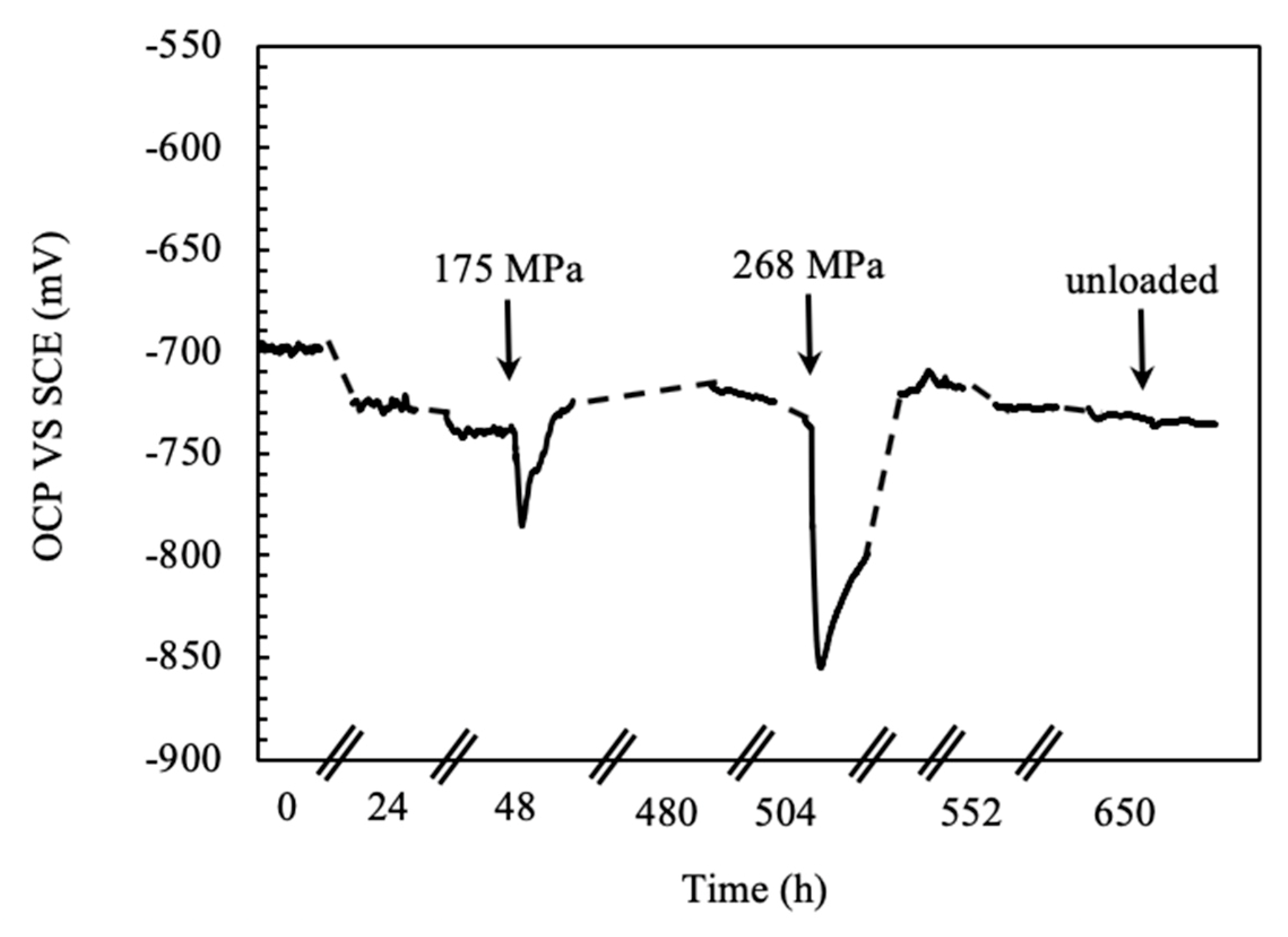
Figure eight. Corrosion morphology of FSWed AA-2024 T3 alloy subsequently CL exam in aerated 35 1000/Fifty NaCl.
Figure 8. Corrosion morphology of FSWed AA-2024 T3 alloy afterward CL test in aerated 35 g/L NaCl.

Figure 9. Metallographic department of Figure 6: (a) Macro image of the nugget with several localized attacks; (b) shut-up of the red zone in (a).
Figure nine. Metallographic section of Figure 6: (a) Macro paradigm of the nugget with several localized attacks; (b) close-up of the ruby zone in (a).
Effigy 10. EIS spectra (a), (c), and (e) Nyquist representation, (b), (d), and (east) Bode representation of the constant load specimen without load only dipped and afterwards 24 h (a,b), after 48 h without load, and after 175 MPa, and after 480 h loaded at 175 MPa (a,d) and afterward 480 h at 175 MPa and 650 h at 268 MPa (east,f) in aerated NaCl 0.6 M solution.
Figure 10. EIS spectra (a), (c), and (due east) Nyquist representation, (b), (d), and (e) Bode representation of the constant load specimen without load merely dipped and after 24 h (a,b), after 48 h without load, and after 175 MPa, and after 480 h loaded at 175 MPa (a,d) and afterward 480 h at 175 MPa and 650 h at 268 MPa (e,f) in aerated NaCl 0.6 M solution.
Effigy 11. Consequence of the time of immersion on the OCP of un-loaded and loaded 4PBB specimens of the FWSed alloy AA 2024-T3 in aerated NaCl 0.vi M at 23 °C (data obtained by [22]).
Figure 11. Effect of the time of immersion on the OCP of un-loaded and loaded 4PBB specimens of the FWSed alloy AA 2024-T3 in aerated NaCl 0.vi M at 23 °C (data obtained by [22]).
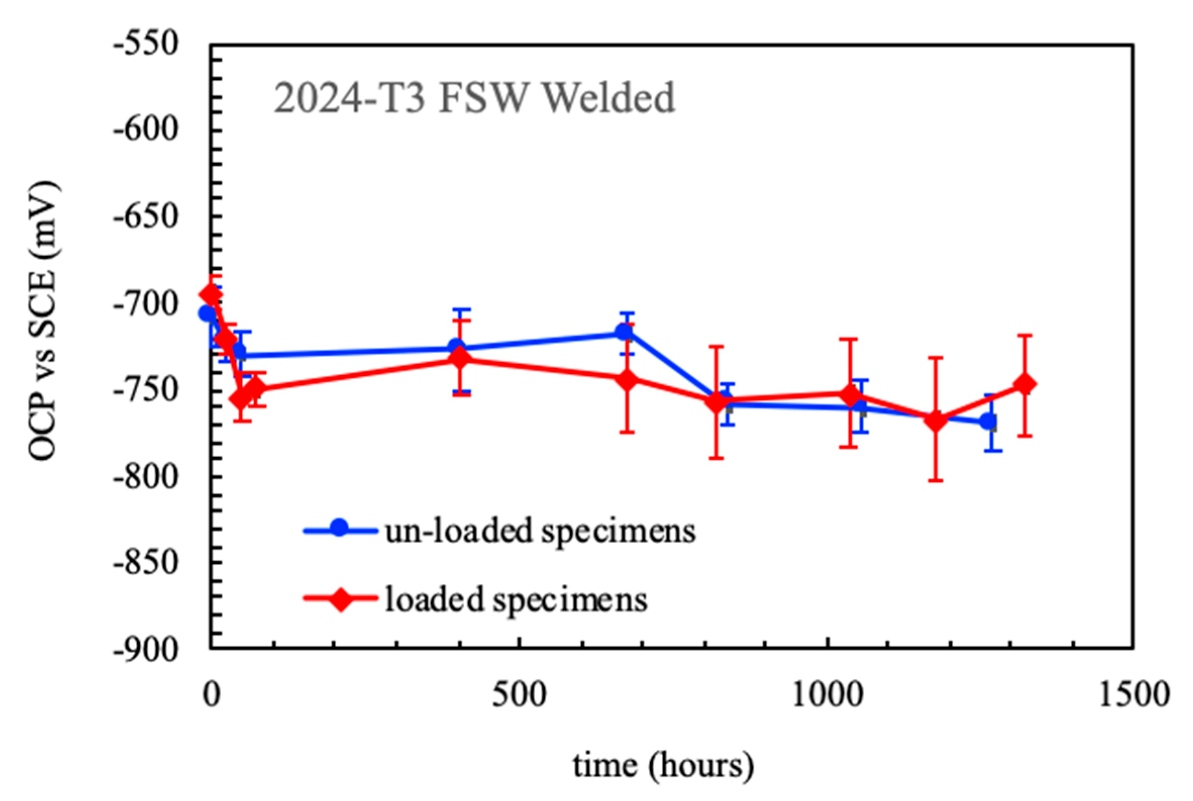
Figure 12. Stress vs. strain and OCP FSWed AA 2024-T3 blend during the SSR examination in aerated NaCl 0.6 M solution at 23 °C.
Figure 12. Stress vs. strain and OCP FSWed AA 2024-T3 alloy during the SSR test in aerated NaCl 0.6 M solution at 23 °C.
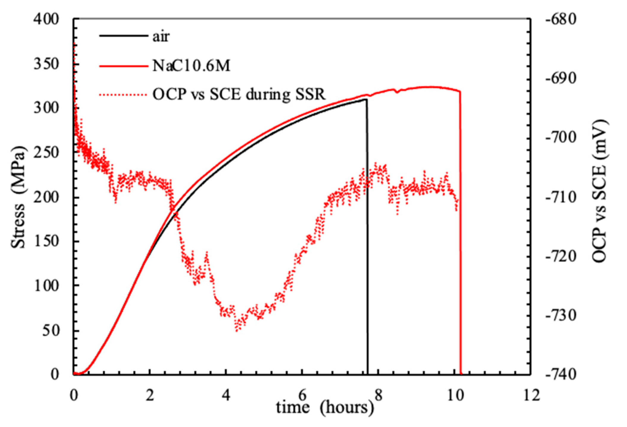
Figure 13. (a) Image of a FSWed specimen after the SSR test in NaCl 35 g/L; (b) close-up of the lateral surface in the correspondence of the fracture surface; (c) close-upward of the dimples in the fully ductile fracture surface; (d) and (e) SCC microcracks in the nugget of the specimen of the FWSed AA 2024-T3.
Figure 13. (a) Image of a FSWed specimen after the SSR test in NaCl 35 g/50; (b) close-up of the lateral surface in the correspondence of the fracture surface; (c) shut-up of the dimples in the fully ductile fracture surface; (d) and (east) SCC microcracks in the nugget of the specimen of the FWSed AA 2024-T3.
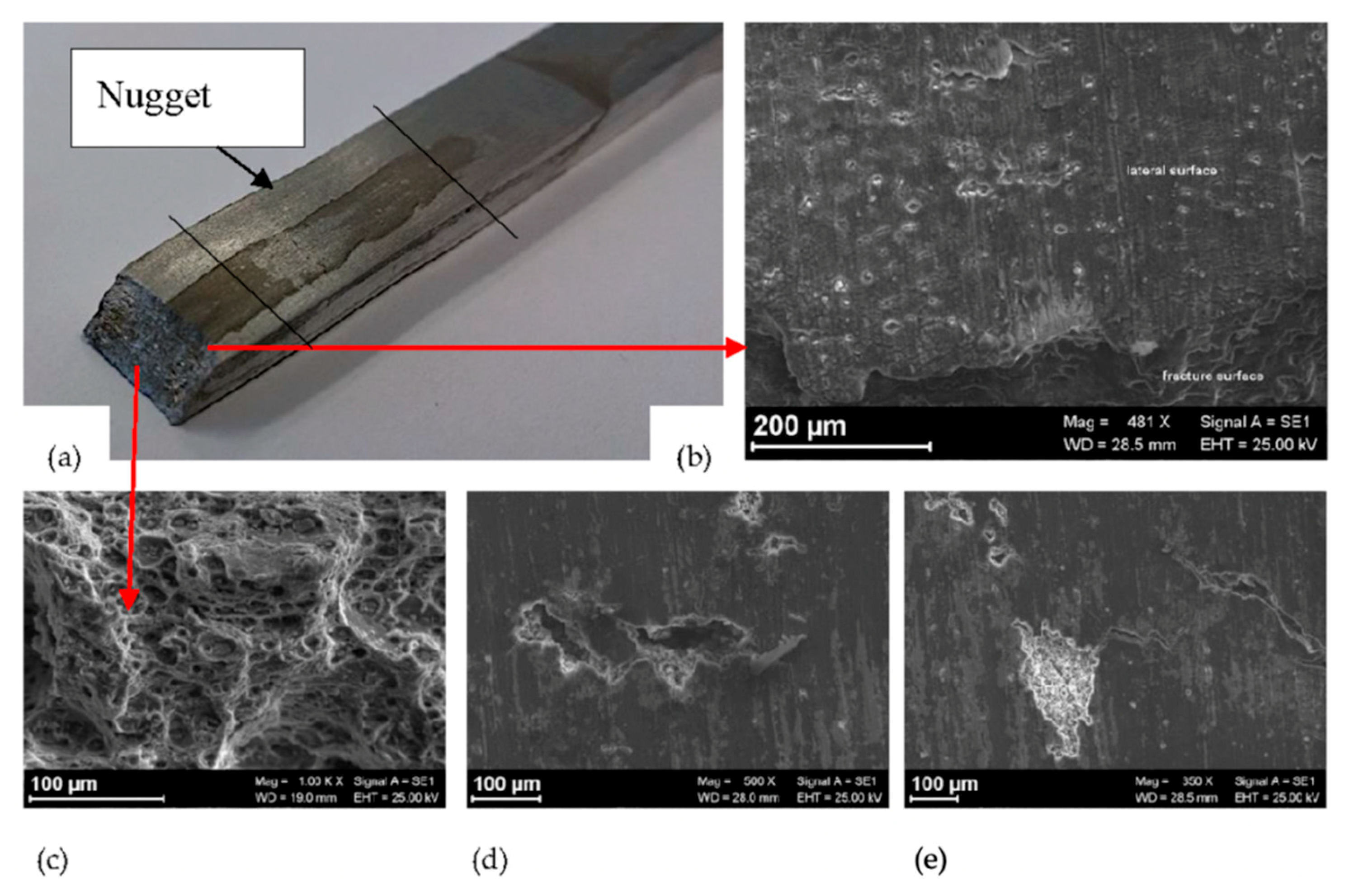
Figure 14. Stress vs. strain and OCP of the base and FSWed AA-2024 T3 blend during the SSR test in aerated NaCl 0.6 M solution at 23 °C.
Effigy 14. Stress vs. strain and OCP of the base and FSWed AA-2024 T3 alloy during the SSR test in aerated NaCl 0.6 M solution at 23 °C.

Figure 15. Microstructure of the AA 2024-T3 alloy (Keller assail).
Figure 15. Microstructure of the AA 2024-T3 alloy (Keller set on).
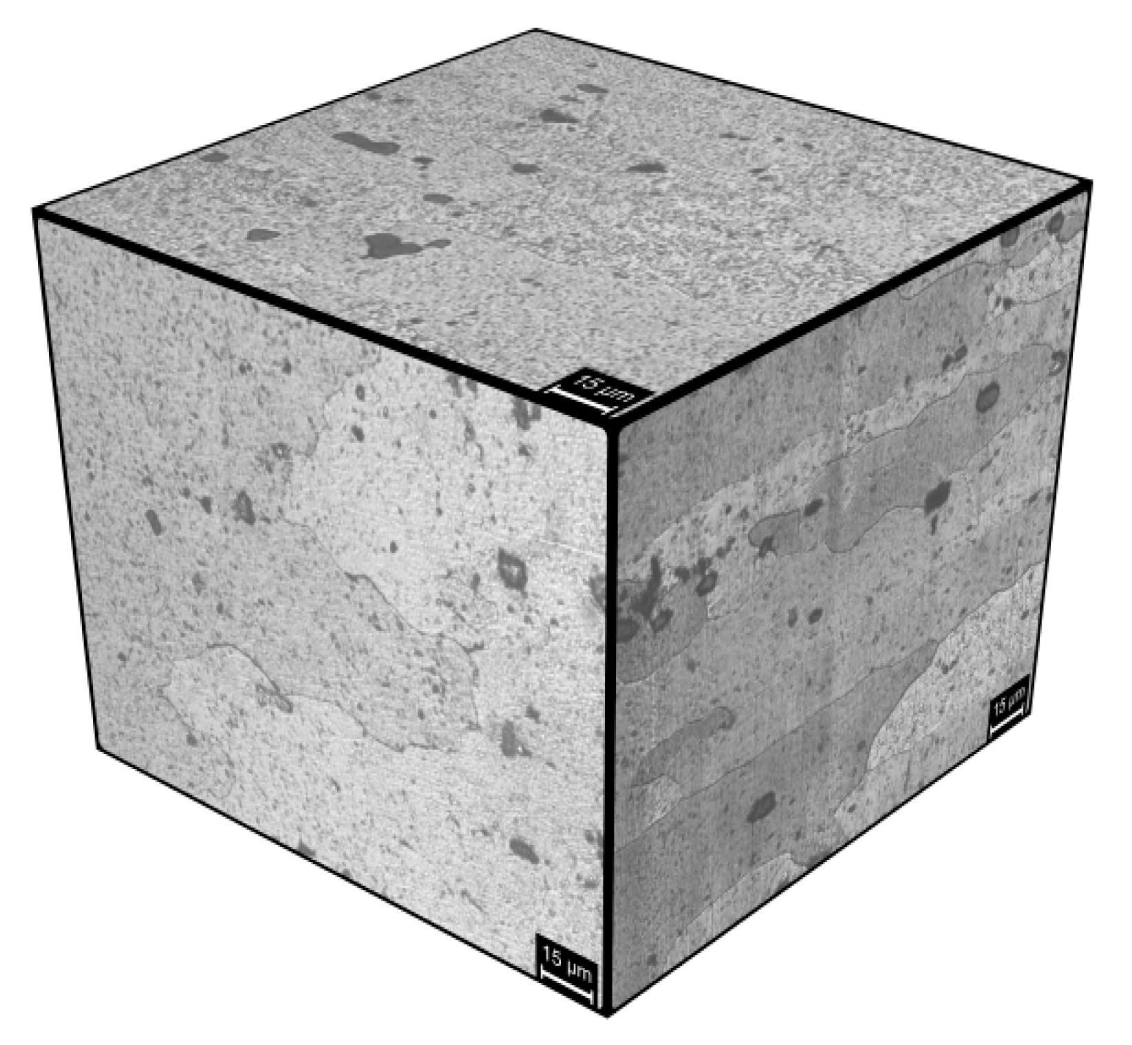
Figure 16. SEM image of the asset without metallographic attack: the brilliant zones are the macro and micrometric precipitates of S-phase.
Figure 16. SEM paradigm of the nugget without metallographic attack: the bright zones are the macro and micrometric precipitates of S-stage.

Table 1. Mechanical properties (yield strength, YS and ultimate tensile strength, UTS) of the base materials and the welded joint.
Table 1. Mechanical properties (yield forcefulness, YS and ultimate tensile strength, UTS) of the base materials and the welded articulation.
| Alloy | Base Material | FSW Joint | |||
|---|---|---|---|---|---|
| YS [MPa] | UTS [MPa] | Max Strain [%] | YS [MPa] | UTS [MPa] | |
| AA 2024–T3 | 345 | 459 | 17 | - | 315 |
© 2020 by the authors. Licensee MDPI, Basel, Switzerland. This article is an open access commodity distributed under the terms and conditions of the Creative Eatables Attribution (CC BY) license (http://creativecommons.org/licenses/past/4.0/).
Source: https://www.mdpi.com/1996-1944/13/11/2610/htm
0 Response to "Electrochemistry Aluminum Corrosion Stress Corrosion Cracking Review Papers"
Post a Comment